After playing with the XBee modules for a while I felt ready to leave the breadboard for a more ‘permanent’ circuit. Remember the wireless temperature sensor built here? My target was to put together some kind of PCB where to connect the XBee end device, the thermistor, the battery case to power the whole stuff and all the other components in order to have something stable and a bit more reliable, I had some tests on battery duration waiting to be performed. And I’d like to put my data on Cosm, too.
However, building a real PCB was out of question: my closet is already full of the chemicals I use for developing and printing my film photographies, adding some more (toxic) things for board etching wouldn’t have been ‘approved’ (just to use a nice word) by the rest of the family.
So I decided to go green and use….cardboard PCB!
As you can see by googling around, this is not anything new: people realized pretty complex stuff using paper and wires, and, quite surprisingly, it works!
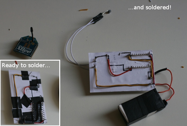
The idea is to have a piece of cardboard where on one side you can put the needed components and on the other you solder the connections using some solid core wire (or, if long enough, connecting directly the components legs to one another) following a point-to-point schema. Nothing too difficult, assumed that your circuit has a low level of complexity.
Designing the ‘PCB’
So, first step is the board. I used piece of very thick paper folded three times and glued together (the glue, once dried, add some more strenght), but here basically anything goes.
Then I used another (thin) sheet to draw the circuit. I bent it in the middle and on one side I added the schematics of the physical components, on the other the connections between them. The idea is put the cardboard between the two parts having components and connections aligned: after drawing the first ones, I put the paper on a light source (my iPad) and checked the wiring diagram to be sure that everything was on the right place.
Since my circuit is very easy, I drew it all by hand: for more sophisticated work you can use some design software, such as Eagle or Fritzing.
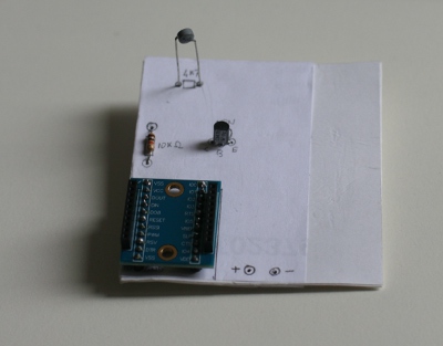
Once the drawings are complete I just glued the paper to the cardboard and pierced it with a needle where I had to insert the physical pieces. In the original design I planned to use a NPN transistor as a switch to open / close the measurement circuit, but later I got rid of it since it wasn’t really beneficial in terms of energy saving.
Adding components
Really not much to say here: I inserted the things in the holes. Below a snapshot of what the board looked like (before removing the transistor):
I placed the connections (solid core wire) on the back following the lines on the paper and keeping them in place with some tape. The thermistor is connected through a couple of stranded wires to allow some degree of freedom on where to place it within the circuit case.
There’s lot of empty space on the board: I left it on porpouse, since sooner or later a few more sensors will join my thermistor.
And finally…
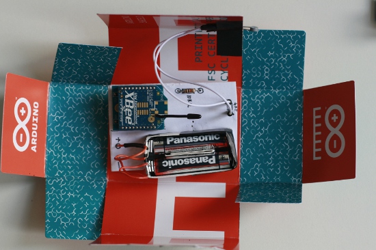
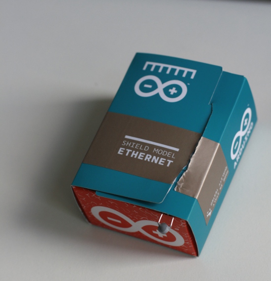
Ok, now it’s ready: time to pack it up on a decent case. The box of an Arduino Ethernet shield I bought to connect to Cosm is exactly the right size (and somehow really meaningful too!):
The thermistor is protruding from the box to keep it away from any thermal dissipation coming from the XBee module, even if it should be really reduced to a minimum since the module itself is idle for the most of the time.
Next episode: how to send the data to Cosm without a PC (the feed coming from my sensor is was here). Stay tuned!


